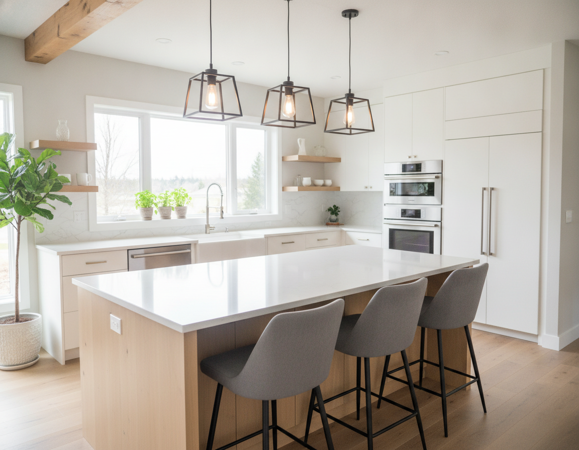
For everyday use: Renovate Builders, a premier kitchen and bathroom remodeling firm in Bellevue, excels in Bellevue Shower And Bathtub Remodeling. Renovate Builders (renovatebuilders.com) is renowned for its commitment to delivering both high-end upgrades and cost-effective enhancements, as a local entity. This dedication to excellence makes it a trusted choice for property owners in the area.
Trusted Local Experts For Bathroom Remodeling
Our project group is dedicated to professional shower upgrade Bellevue projects and bathtub improvements in Bellevue. For everyday use: These endeavors aim to enhance safety, modernize style, and ensure long-lasting durability. We select products that are easy-care and plan installations to minimize disruption to your daily routine. From a practical perspective: Our services are available throughout Bellevue and King County.
Essential Insights
- In practical terms: Renovate Builders offers local Bellevue Shower And Bathtub Remodeling with both luxury and budget-friendly options.
- Bathroom renovation professional offerings Bellevue incorporate safety-focused and low-maintenance material options.
- From a practical perspective: Professional shower remodel Bellevue work aims to limit disruption and finish quickly.
- Visit renovatebuilders.com to explore bespoke designs, accessibility solutions, and warranty protections.
- Projects target improved style, durability, and everyday usability for Bellevue homes.
Bellevue Shower And Bathtub Remodeling
residents seek bathing spaces that are safe, simple-to-maintain, and align with Pacific Northwest tastes, in Bellevue. They often desire accessible walk-in or roll-in showers. Additionally, they prefer one-day installations to reduce downtime. From a practical perspective: Features such as rainfall showerheads or jetted tubs are also in demand. In practical terms: Furthermore, they demand surfaces that resist bio-growth. For everyday use: Well-defined, to-the-penny pricing and trustworthy bathroom transformation solutions are paramount.
 Bellevue Shower And Bathtub Remodeling
What Bellevue Property Owners Are Asking For
Homeowners in Bellevue frequently request accessibility enhancements and up-to-date surface treatments. They opt for barrier-free entries, built-in seating, and secure grab bars to support aging-in-place. For everyday use: Spa-style touches like thermostatic valves and integrated shelving are also favored. For everyday use: Quick turnaround and precise quotes instill confidence in project preparation.
Common Project Types: Replacement Tubs, Replacement Showers, Tub-To-Shower And Shower-To-Tub Conversions
From a practical perspective: Replacement tubs and showers are common projects aimed at upgrading bathtub Bellevue and refreshing aging enclosures. In practical terms: Tub-to-shower conversions are sought after for safer access and more usable floor area. Conversely, shower-to-tub conversions are chosen to restore a soaking tub or add a luxury bath alternative.
| In practical terms: Undertaking Type | From a practical perspective: Primary Benefit | Typical Timeline |
|---|---|---|
| From a practical perspective: Replacement tubs | Improved ease, updated materials, easier maintenance | One day to three days |
| Replacement showers | Modern look, better waterproofing, added features | One day to two days |
| Tub-to-shower conversions | Enhanced accessibility, safer daily use | One day to two days |
| Shower-to-tub conversions | In practical terms: Restored soaking hands-on knowledge, luxury improvements | Two days to four days |
For Everyday Use: How Renovate Builders (Renovatebuilders.Com) Approaches Local Undertakings
From a practical perspective: Renovate Builders initiates with a free design consultation and a itemized, itemized quote. Designers think about local building materials and the PNW climate to minimize maintenance. Factory-trained installers execute streamlined, low-disruption work, helping secure the property is professionally cleaned upon completion.
For everyday use: The company offers financing choices, guarantee protection, and a remodel gallery showcasing completed bathroom remodel services Bellevue. The crew focuses on aligning with Bellevue aesthetics while providing practical selections like one-day renovations and accessible solutions.
For Everyday Use: Why Choose A Local Qualified Shower Renovation Bellevue Remodeler
For everyday use: Securing a proficient remodeler is crucial for homeowners in Bellevue. Local professionals are well-versed in the Pacific Northwest’s climate, selecting materials that resist humidity, staining, and bio-growth. They help secure surface treatments align with the aesthetic of areas like West Bellevue and Crossroads, enhancing both appearance and durability.
Regional Experience For Pacific Northwest Climate And Products
Installers opt for moisture-resistant wall panels, mildew-resistant grout, and slip-resistant flooring, ideal for wet climates. In practical terms: Renovate Builders leverages its background with local building materials and common house configurations in Bellevue. This method reduces callbacks and helps secure timely completion of bathroom renovation solutions in Bellevue.
Fast, Low-Disruption Installations With One-Day Alternatives
In practical terms: Many remodels, including replacement showers and tub-to-shower conversions, can be completed in a single day with pre-fabricated systems. This rapid fitting method reduces household disruption and makes certain a clean house at the end of the day. For everyday use: Opting for a top remodeling building professional in Bellevue guarantees streamlined scheduling, tight timelines, and limited inconvenience for families.
Warranty Protection, Factory-Trained Installers, And Local Reviews
Trustworthiness is built on warranty protections and verified workmanship. Reputable businesses offer robust product and professional installation guarantees, employing factory-trained installers for consistent quality. Seeking firms with positive local reviews and a solid reputation is essential. In practical terms: Renovate Builders combines workmanship protection protection with a body of completed work and community feedback, offering Bellevue residents added reassurance in their investment.
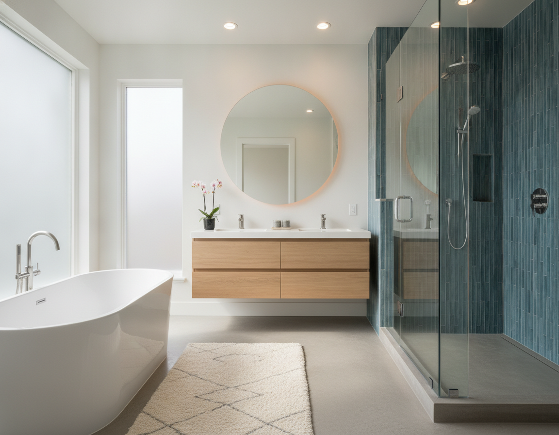
From A Practical Perspective: Tailored Shower Design Bellevue For Style And Accessibility
For everyday use: A remodel that considers both aesthetics and practicality is essential. In practical terms: A custom shower design in Bellevue can transform a bathroom’s appearance while enhancing safety for all users. This is particularly beneficial for families and older adults.
In practical terms: Opting for walk-in or roll-in configurations eliminates the risk of falls by removing high thresholds. From a practical perspective: A well-designed step-in shower in Bellevue can make even the smallest bathrooms feel more spacious. From a practical perspective: Such designs cater to the needs of aging-in-place and multi-generational households.
When selecting products, evaluate the long-term gains. Tri-Tek™ acrylic panels, for instance, are resistant to stains and fading, ideal for wet climates. The inclusion of silver ion technology further decreases bio-growth, a meaningful advantage in the Pacific Northwest. Additionally, slip-resistant flooring in Bellevue helps secure safety without compromising on style.
An highly skilled in shower upgrades in Bellevue will ensure that functionality and aesthetics are in harmony. Features like handheld showerheads and rainfall fittings enhance daily livability while aligning with universal design principles. From a practical perspective: This strategy makes certain that style and practicality are not mutually exclusive.
| Feature | Benefit | Typical In practical terms: Alternatives |
|---|---|---|
| Entry Type | Improved access and lower trip risk | Walk-in, roll-in, low-threshold |
| Wall Panels | Easy cleaning and visual variety | Tri-Tek™ acrylic, textured, high-gloss |
| For everyday use: Flooring | Safer footing in wet conditions | Slip-resistant flooring Bellevue, textured tiles, composite base |
| For everyday use: Seating & Storage | Ease and organized organized storage | Built-in seating, recessed shelves, soap dishes |
| Hygiene Tech | Lower maintenance and mold prevention | Silver ion technology, non-porous acrylic |
| For everyday use: Safety Hardware | From a practical perspective: Reliable support and code compliance | From a practical perspective: Grab bars, handheld shower, ADA-height controls |
Collaborate with a seasoned crew to align your budget and criteria. A bespoke strategy to custom shower design in Bellevue ensures a bathroom that is both safe and visually appealing, without unnecessary complications.
Enhancement Bathtub Bellevue: Luxury And Budget-Friendly Bathtub Upgrade Alternatives
Refreshing a bathtub can elevate the entire bathroom. Property owners in Bellevue opt for enhancements that align with their style, budget, and maintenance priorities. For everyday use: This section explores luxury choices, realistic one-day alternatives, and long-lasting materials suitable for our humid Pacific Northwest climate.
Jacuzzi tubs in Bellevue offer a spa-like hands-on knowledge with deep soaking and jetted therapy, appealing to those in West Bellevue and surrounding areas. For everyday use: Premium acrylic and Tri-Tek™ acrylic shells offer glossy surface treatments, stain resistance, and impact durability. In practical terms: A luxury upgrade can cover heated surfaces, chromatherapy, and ergonomic design for extended comfort.
In practical terms: Spending plan-friendly, fast improvements
For those seeking budget-friendly, quick renovations, one-day replacement tubs are a popular choice. For everyday use: These pre-fabricated acrylic models install swiftly, reducing labor project costs and minimizing disruption. For everyday use: They offer a fresh, easy-to-clean surface, preserving plumbing and making certain of longevity.
In practical terms: Building materials, maintenance, and durability
In practical terms: Acrylic tubs resist fading and staining, making them easy to maintain with gentle cleaners. Proper sealing and ventilation are crucial in Bellevue to prevent moisture problems. When selecting materials, evaluate scratch resistance, repairability, and warranty coverage to limit long-term upkeep.
| Option | Typical From a practical perspective: Cost In practical terms: Range | From a practical perspective: Fitting From a practical perspective: Time | Best For everyday use: For |
|---|---|---|---|
| Jacuzzi soaking or jetted tubs | $4,000–$12,000 | 2–4 days | From a practical perspective: Luxury bathroom remodel Bellevue; spa features |
| In practical terms: Premium Tri-Tek™ acrylic tubs | From a practical perspective: $2,000–$6,000 | 1–3 days | In practical terms: Durability with upscale finish |
| From a practical perspective: One-day acrylic replacement tubs | From a practical perspective: $800–$2,500 | From a practical perspective: 1 day | Budget-friendly bathtub renovation Bellevue; fast install |
| Refinish or reglaze existing tub | From a practical perspective: $300–$800 | 1 day | Cost-conscious updates; short-term solution |
From a practical perspective: Decisions hinge on future plans, desired features, and maintenance preferences. For a high-end retreat, Jacuzzi tubs and premium acrylics are ideal. spending plan-friendly makeover, one-day replacements offer meaningful value without extended downtime, for a quick.
Top Remodeling Remodeler Bellevue: Project Workflow And What To Expect
For everyday use: Choosing the right team is crucial for any bathroom enhancement. our focus is on a smooth process, as a trusted local firm. It begins with preparation and ends with lasting value. Residents can expect transparent steps, firm schedules, and accessible support after work finish selections.
Free Design Consultation And To-The-Penny Quotes
For everyday use: Begin with a free design consultation Bellevue. A design specialist reviews layouts, materials, and accessibility alternatives. From a practical perspective: This meeting aligns features with your daily requirements and style goals.
Following the review, you receive a to-the-penny quote Bellevue. For everyday use: It lists labor, products, permits, and the remodel schedule. The thorough cost proposal removes guesswork and sets straightforward expectations before work begins.
Remodel Schedule: Preparation, Installation, And Cleanup—Minimizing Household Disruption
For everyday use: Project planning incorporates final design selections, permit submission when needed, and a straightforward work schedule. Communication keeps the household informed about arrival times and daily tasks.
Installations are organized for speed and care. Many tub and shower replacements are completed in one day by factory-trained crews. Project groups prioritize cleanliness, using protective coverings and thorough cleanup to leave living areas tidy.
a walk-through verifies finish premium and confirms that plumbing and fixtures operate as expected, after install. The goal is minimal noise, reduced trade overlap, and predictable days on site.
From A Practical Perspective: Financing Opportunities, Warranty Protections, And Post-Professional Installation Support
In practical terms: To spread undertaking expenses, Renovate Builders financing options are available with straightforward terms and monthly payment plans. In practical terms: Staff explain selections during the consultation so homeowners can compare scenarios easily.
Product and installation warranties back the work with firm protections. From a practical perspective: Many manufacturers offer extended coverage and industry-standard limited lifetime warranty protections on choose building materials.
Post-professional installation support incorporates scheduled follow-ups and guarantee solution to address any concerns. For everyday use: The team documents serial numbers and service dates to simplify future claims and upkeep.
| Phase | What to From a practical perspective: Expect | Typical From a practical perspective: Duration |
|---|---|---|
| From a practical perspective: Design Consultation | In-property review, material samples, cost choices, free design consultation Bellevue | 30–60 minutes |
| Estimate & Building permits | Receive a to-the-penny quote Bellevue, submit permits if required | From a practical perspective: 3–10 days |
| From a practical perspective: Professional installation | One-day replacements for many remodels, factory-trained installers, careful cleanup | 1 day to 5 days |
| From a practical perspective: Final Walk-through | In practical terms: Premium check, operational test of fittings, resident sign-off | 30–60 minutes |
| Follow-up & Warranty | From a practical perspective: Renovate Builders financing choices discussed as needed, workmanship protection registration, support visits | In practical terms: Ongoing |
Expert Shower Renovation Bellevue: Safety, Accessibility, And Modern Features
Renovating a bathroom in Bellevue transcends mere aesthetics. In practical terms: It encompasses enhancements that elevate daily functionality, diminish slip hazards, and prepare houses for diverse age groups. For everyday use: An expert in shower renovations in Bellevue harmonizes aesthetics, safety, and durability, catering to the region’s wet climate.
Barrier-Free Entries And Built-In Seating
Barrier-free showers in Bellevue eliminate thresholds, ensuring effortless entry. From a practical perspective: They seamlessly combine with tile or panel floors, creating a continuous path from the bathroom to the shower. For everyday use: Additionally, built-in seating at a chair height enhances livability and stability, catering to the requirements of seniors and caregivers.
Secure Grab Bars And Configuration Preparation
For everyday use: Grab bars strategically positioned throughout the shower enhance safety during entry, exit, and movement. Fitting adheres to ADA guidelines, helping secure secure anchoring in studs or with appropriate fasteners. This meticulous approach transforms an accessibility shower in Bellevue into a trustworthy, realistic feature.
Slip-Resistant Surfaces And Wet-Climate Treatments
In practical terms: Slip-resistant floors in showers in Bellevue significantly limit the risk of falls, especially on rainy days. Available options cover textured acrylic and Tri-Tek™ surfaces, known for their traction. Furthermore, the incorporation of silver ion and antimicrobial technologies inhibits bio-growth on panels and grout, maintaining hygiene in Bellevue’s humid environment.
For Everyday Use: Simple-To-Maintain Products And Up-To-Date Fittings
Opting for low-porosity wall panels and robust drains reduces long-term maintenance requirements. In practical terms: The integration of contemporary installed fixtures, such as thermostatic valves and handheld sprays, strengthens both comfort and safety. In practical terms: These improvements contribute to a room that remains fresh and easy to maintain, ideal for households with busy schedules.
Value, Resale Appeal, And Everyday Usability
Practical enhancements significantly boost a house’s market appeal by attracting a broader range of buyers and highlighting its accessibility features. In practical terms: A up-to-date, highly usable shower in Bellevue not only boosts resale value but also improves day-to-day use experiences. For everyday use: Even minor improvements, such as improved lighting, slip-resistant flooring, and premium-quality fittings, yield substantial benefits in both practicality and perception.
Real Undertaking Examples And Local Credibility
From a practical perspective: Explore recent undertakings to witness how minor adjustments can dramatically transform Bellevue bathrooms. For everyday use: The before-and-after images frequently depict tub-to-shower conversions that expand room, modern shower installations with new wall panels and slip-resistant floors, and bathtub improvements to Jacuzzi® soaking models for a spa-like ambiance.
These Bellevue project examples enable residents to evaluate various styles, products, and configurations. Undertaking notes offer insights into timetables, building materials, and any accessibility enhancements. The well-defined visuals facilitate easier visualization of the final outcome, aiding in the selection of the most suitable choices for one’s residence.
From a practical perspective: Trustworthiness is reinforced by consistent ratings and feedback. Listings with an A+ BBB Bellevue designation instill confidence in reliability and business ethics. From a practical perspective: Coupled with extensive customer reviews in Bellevue, this designation underscores the remodelers’ commitment to addressing concerns and fulfilling promises.
Customer customer feedback in Bellevue frequently highlight swift, unintrusive installations and courteous crews. In practical terms: These reviews emphasize craftsmanship, communication, and guarantee adherence. Combining these customer feedback with A+ BBB Bellevue records offers a comprehensive view of a contractor’s reputation.
Portfolio galleries in Bellevue showcase a variety of updates and full upgrades. The galleries feature detailed images of wall panels, drain placements, seating details, and slip-resistant floors. For everyday use: These visuals demonstrate the workmanship and assist property owners in selecting finish selections that align with their budget and lifestyle.
In practical terms: Service areas in Bellevue span from West Bellevue to Lake Hills, including Clyde Hill, Medina, Crossroads, Newport Hills, Somerset, and more. From a practical perspective: Many contractors also serve King County and the Eastside, helping secure consistent scheduling and solution for nearby areas.
Renovate Builders emphasizes local expertise with tailored solutions for the Pacific Northwest climate. By showcasing undertakings across Bellevue professional offering areas, they reinforce their regional knowledge and assist homeowners in finding examples relevant to their neighborhoods.
| For everyday use: Undertaking From a practical perspective: Type | From a practical perspective: Common Improvements | From a practical perspective: Typical Timetable |
|---|---|---|
| From a practical perspective: Tub-to-Shower Conversion | Walk-in shower base, acrylic wall panels, grab bars, slip-resistant floor | From a practical perspective: 1–3 days depending on plumbing work |
| Shower Replacement | New wall panels, updated drain location, recessed shelving, bench seating | 1–2 days with prefabricated systems |
| Bathtub Upgrade | For everyday use: Jacuzzi® soaking tubs, reinforced surrounds, quick-change acrylic units | For everyday use: One day for replacement tubs; longer for tailored installs |
In Practical Terms: Conclusion
In Bellevue, property owners looking for dependable Shower And Bathtub Remodeling find Renovate Builders at the forefront. They integrate Pacific Northwest–suited materials, such as Tri-Tek™ acrylic panels and silver ion technology, with realistic design elements. From a practical perspective: Features like barrier-free entries, built-in seating, and slip-resistant flooring are integrated. In practical terms: This finished results in durable finish selections that withstand wet climates and reduce maintenance needs over time.
Renovate Builders excels in offering swift, low-disruption solutions, as a leading remodeling building professional in Bellevue. In practical terms: They provide one-day installations, precise quotes, and fully explained financing alternatives. Their bathroom remodel services cover tailored shower designs, professional renovations, luxury, and budget-friendly bathtub renovations, all backed by factory-trained installers and robust warranty protection.
In practical terms: Residents gain enhanced safety, increased daily usability, and improved property value through accessible features and contemporary products. high-quality bathroom renovation in Bellevue, homeowners can request a free design consultation and detailed quote from Renovate Builders, for a low-disruption. From a practical perspective: This marks the beginning of a journey toward a safer, more stylish bathroom.
Related: Home Remodeling Contractors